HyperLED-Plugin-Klipper-Status
HyperLED plugin: shows the state of a Klipper 3D printer (via Moonraker).
There is now a light bar under the print bed of my Snapmaker U1 that shows me with light how far the print has got. The parts come from drc85, and HyperLED controls it.
A print often takes hours. The bar shows the progress as a bar that grows from left to right. You can see it from a few meters away, and I find that really handy.
The idea and the printed parts come from drc85. A HyperLED board running my Klipper Status plugin controls the bar.
| Printer | Snapmaker U1 |
|---|---|
| Firmware | Extended Firmware by paxx12 |
| Display | Progress bar under the print bed |
| Controller | HyperLED on ESP32-C6 Super Mini |
| Software | Klipper Status plugin |
| Printed parts | by drc85 (MakerWorld) |
| Mounting | 3M VHB 5952, double-sided |
| Cable | USB, 1 m, routed so it cannot jam |
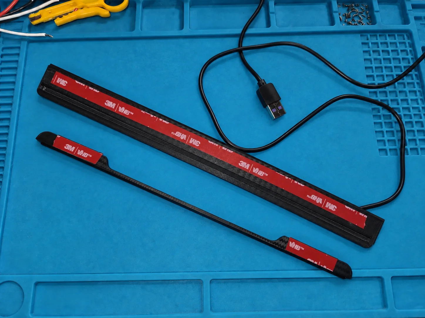
The bar sticks well under the print bed. This needs a double-sided tape that can withstand high temperatures. I chose one made with the material 3M VHB 5952.
When sticking it on, make sure the cable cannot jam anywhere, so that the print bed can always move freely. I simply looked at how the print bed's heater cable is routed.
The video shows a whole print as a time-lapse (10x) and what the bar shows at each point. The colors for each state can be chosen freely in the plugin. See the description of my plugin for that.
| Idle | a dim dark blue |
|---|---|
| Preheating | an orange bar that breathes slowly and gets longer as the heaters get closer to their targets |
| Printing | a green bar that grows with the progress |
| Paused | the whole bar breathes yellow |
| Finished | the whole bar glows cyan until the printer goes idle |
| Error | the whole bar flashes red |
| No connection | bar off, for example when the printer is switched off |
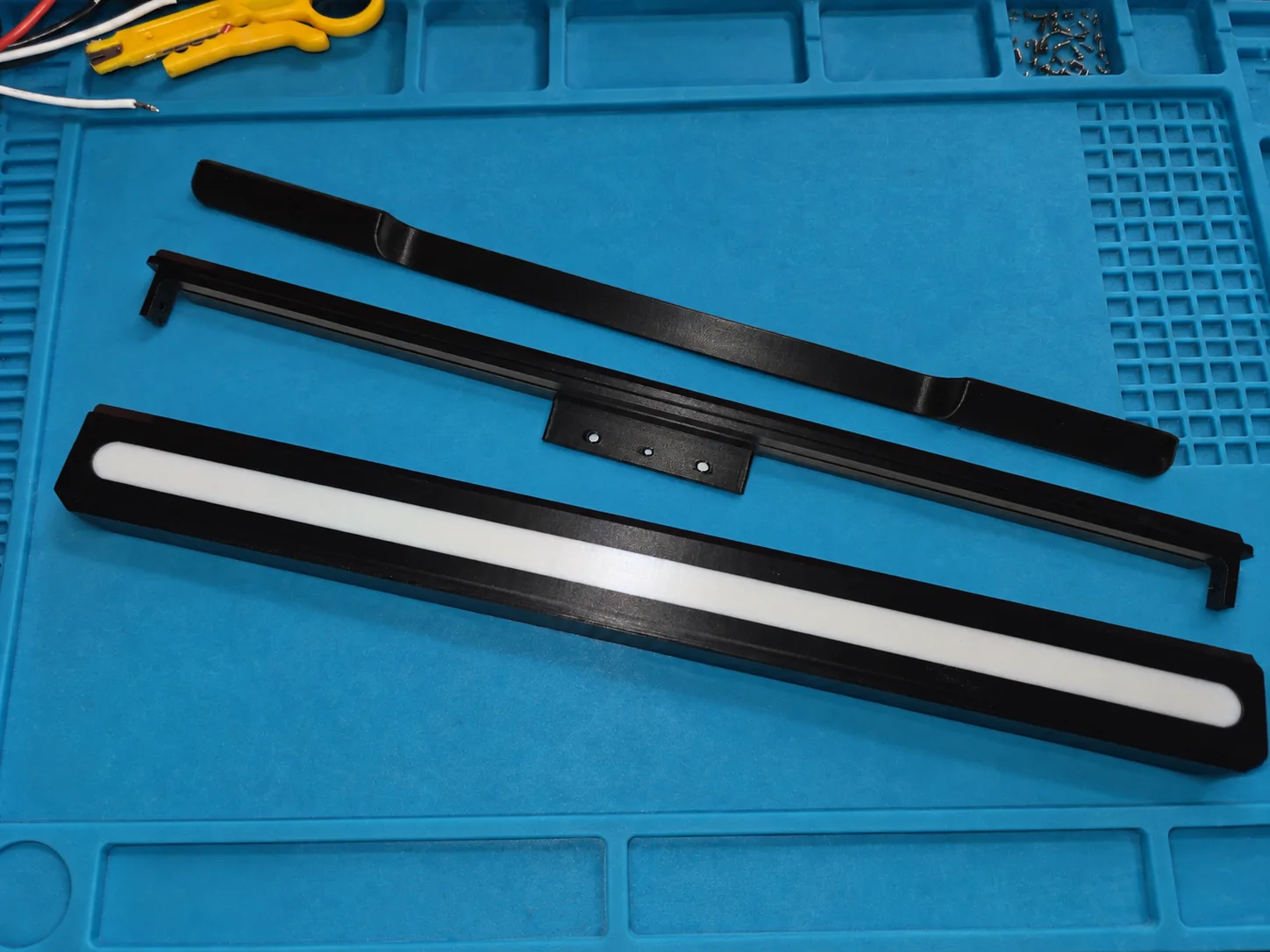
I downloaded the STL files by drc85 from makerworld.com and printed them. I deliberately chose the version that mounts under the bed, because all the other spots on my printer are already taken. I printed them with the standard print profile of the Snapmaker U1, in PLA. I will report back if PLA does not handle the temperatures so well.
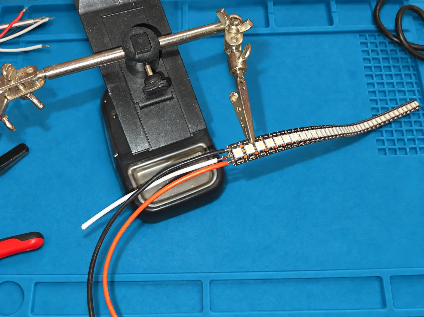
I soldered the resistor directly to the LED strip, because I only had small SMD resistors at hand. I then had to bend everything backwards so the wires fit through the opening in the housing.
The wires I chose are quite thick, you can easily use thinner ones. The Snapmaker's USB port only supplies 0.5 A at 5 V.
As the brain I used an ESP32-C6 Super Mini from Waveshare. It fits into the housing nicely, so I do not have to find a place for it somewhere else.
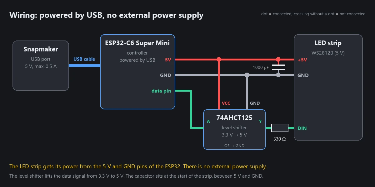
The ESP32 is powered through the Snapmaker's USB port, I do not use an external power supply. The LED strip gets its power from the 5V and GND pins of the ESP32-C6. The data signal goes from the ESP32 through a level shifter (74AHCT125), which lifts it from 3.3 V to 5 V, and through the 330 Ω resistor to the strip's data input. At the start of the strip a 1000 µF capacitor sits between 5 V and GND.
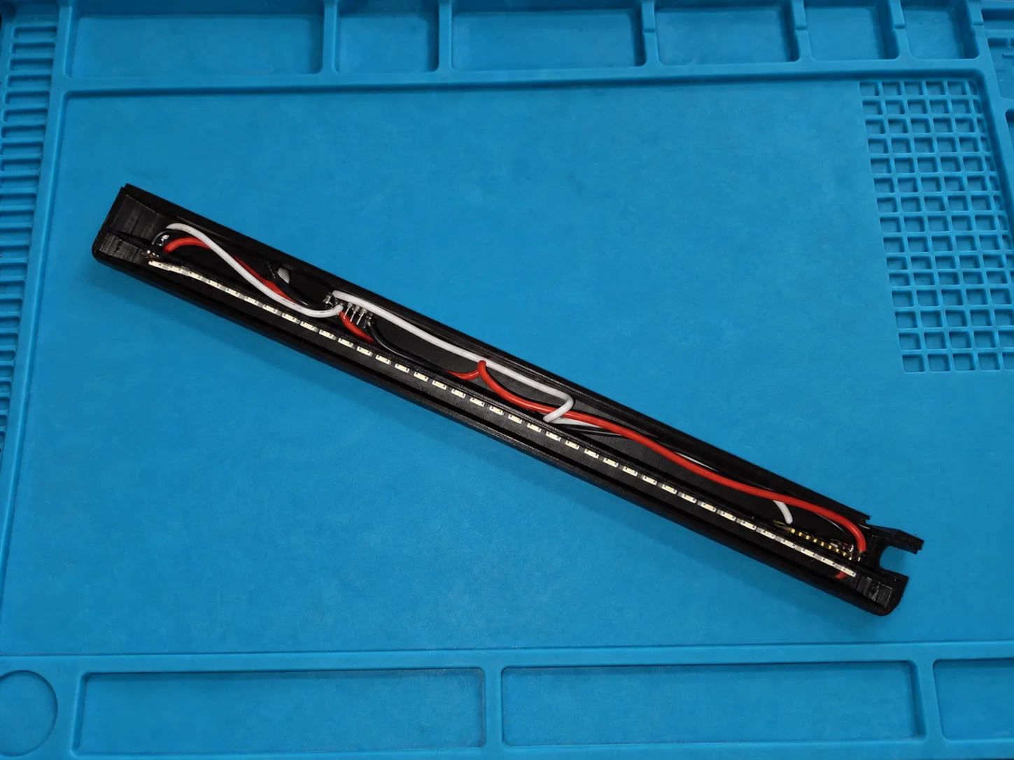
There is not much room, especially if you chose such a large cross-section for the wires as I did. With some careful pressing it works quite well, though.
The whole controller sits in the rear chamber, and I carefully pressed the LED strip into place with tweezers.
The parts get double-sided 3M VHB 5952 tape. Since the build chamber gets hot, the tape should be suitable for that if you choose a different one.
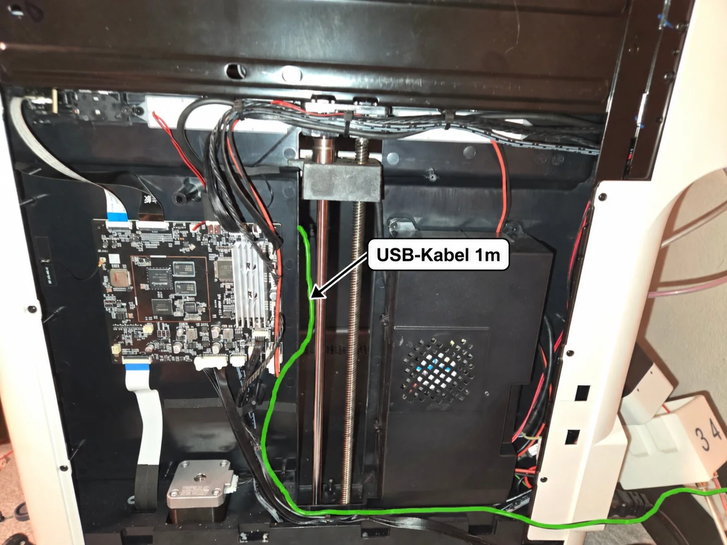
The USB cable (1 m) runs along the back. The green line in the photo shows its path. I fastened the cable at the bottom to the other cables with a cable tie. Make sure there is enough slack in the cable and that it cannot get caught anywhere. I then ran it along under the power supply and out through the opening for the feeders' ribbon cable.
The cable is then long enough to plug it into the USB port.
The printed parts come from drc85, not from me. You find them on MakerWorld: Snapmaker U1 SnapStatus LED Status Bar. The source code is on GitHub.
His model is made for WLED. In my build, HyperLED controls the bar.
A HyperLED board sits behind the bar. My Klipper Status plugin asks the printer for its state every five seconds and turns it into the picture on the bar. More on the plugin's own page.
On the Snapmaker U1 the plugin only works with the Extended Firmware by paxx12. It comes from the community and not from Snapmaker. Read its notes before you install it.
If the LED strip hangs on USB without a strong supply of its own, LEDs behind the end of the bar can flash briefly. The resistor in the data line, the capacitor and the level shifter help against that.
HyperLED plugin: shows the state of a Klipper 3D printer (via Moonraker).
LED controller for ESP32-S3 boards. Inspired by the WLED project, but with different features.