Wiring and power
Good wiring decides whether your LEDs run smoothly or flicker. It is not hard: three connections are enough.
Never power the LEDs from the ESP32. The board cannot supply that much current and can be damaged. The strip gets its own power supply. The ESP32 only sends the data signal, and shares ground with the power supply.
The basic wiring
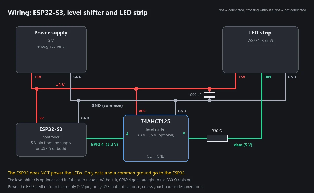
| From | To | Wire |
|---|---|---|
| Power supply +5 V | strip +5 V | thick |
| Power supply GND | strip GND | thick |
| Power supply GND | ESP32 GND | thin (this is the "common ground") |
| ESP32 GPIO 4 | strip DIN (data in), through a 330 Ω resistor close to the strip. With a level shifter (see below): GPIO 4 → shifter input A, shifter output Y → resistor → DIN | thin |
| (optional) Level shifter 74AHCT125 | VCC to +5 V, GND to GND, OE to GND (enables the channel); unused inputs to GND | thin |
| Capacitor 1000 µF | across the strip's +5 V and GND, close to the strip's start | mind the polarity: the stripe on the capacitor marks the minus side |
The ESP32 needs power too. There are two ways, and you choose one:
- By USB, for example from a charger or from your computer.
- From the power supply: connect the supply's +5 V to the ESP32's 5 V pin (as in the diagram). The ground is shared anyway.
Do not use both at the same time, unless your board's documentation says it is designed for that.
Things to check:
- Data direction: LED strips have an arrow. Connect the ESP32 to the end that says DIN (or DI), not DOUT.
- Short data wire: keep it short, ideally under 30 cm. Longer wires pick up interference.
- 12 V strips (WS2815 and similar) need a 12 V supply. Do not mix voltages: the ESP32 only shares the ground with them.
- Backup data line (BIN) on WS2813/WS2815: it does not need an ESP32 pin. Connect it to GND, or together with the data wire.
Why the resistor, capacitor and level shifter?
- Resistor (about 330 Ω) in the data line, close to the first LED of the strip, calms the signal and protects the first LED from voltage spikes.
- Capacitor (1000 µF) across the power input buffers the current spike when the strip switches on.
- Level shifter (74AHCT125): the ESP32 sends data at 3.3 V, while WS2812B strips officially expect 5 V. It often works without a level shifter. If your LEDs flicker or show random pixels, a level shifter fixes it in most cases.
The 74AHCT125 is a small chip with four independent channels; you only use one. It is powered with the strip's 5 V, so it turns the ESP32's 3.3 V signal into a clean 5 V signal. In the diagram: pin 1 (OE) to GND, pin 2 (A) from GPIO 4, pin 3 (Y) to the resistor and on to DIN, pin 7 to GND, pin 14 to +5 V; tie the inputs of the three unused channels (pins 5, 9, 12) to GND. Make sure it is the AHCT type (a plain 74HC125 does not reach 5 V levels from 3.3 V reliably). Ready-made one-channel or four-channel level shifter boards work as well.
12 V and 24 V strips
Strips such as WS2815 (12 V), WS2805 (12 V) and 24 V strips need a power supply of their own voltage. The ESP32 and the level shifter must never get 12 V or 24 V: they need 5 V. A small buck converter (step-down module) makes it from the supply's voltage.
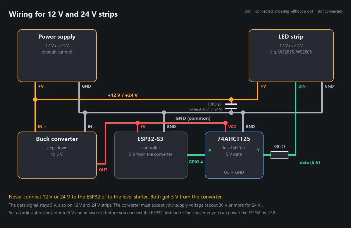
| From | To | Wire |
|---|---|---|
| Power supply +12 V / +24 V | strip +V and buck converter IN + | thick (strip) / thin (converter) |
| Power supply GND | strip GND, converter IN −, ESP32 GND, level shifter GND | thick (strip) / thin (others) |
| Buck converter OUT + (5 V) | ESP32 5 V pin and level shifter VCC | thin |
| ESP32 GPIO 4 | level shifter A; shifter Y → 330 Ω resistor → strip DIN | thin |
| Capacitor 1000 µF | across the strip's +V and GND, close to the strip's start | rated for the voltage: 16 V or more for 12 V, 35 V or more for 24 V |
Choosing the buck converter:
- It must accept your supply voltage with room to spare: for 12 V a module rated for at least 18 V, for 24 V one rated for 30 V or more (many cheap modules take up to 36 or 40 V).
- Its output must be 5 V. With an adjustable module, set it to 5 V and measure it before you connect the ESP32 and the level shifter.
- 1 A is plenty for the ESP32 and the level shifter. The LEDs do not draw from the converter.
Good to know:
- The data signal stays 5 V, also on 12 V and 24 V strips. Never put 12 V or 24 V on the data pin.
- As with 5 V strips, the level shifter is optional: add it if the strip flickers.
- Instead of the converter you can power the ESP32 by USB; the level shifter then takes its 5 V from the USB 5 V pin of the board.
- In the web interface, 12 V and 24 V strips often need the setting LEDs per chip (Devices → LED hardware): on common 12 V strips one chip drives 3 LEDs, on 24 V strips 6 (or 7 with 84 LEDs per metre). See First light.
- Feed long strips from both ends, as described below. Ground stays connected everywhere.
Strip power: feed long strips from several points
Over a long strip the voltage drops, and the far end looks reddish or dim. For long strips, connect the power supply at both ends (or every 2 to 3 metres) with thick wires. Always keep the grounds connected.
Default pins
You can change these in the web interface.
| Function | Default pin (ESP32-S3) |
|---|---|
| LED data | GPIO 4 (you can pick another one in Devices → LED hardware) |
| Input 1 (push button) | GPIO 39 (switches to GND; switched on in the web interface) |
| Input 2 (switch) | GPIO 40 (switches to GND; switched on in the web interface) |
HUB75 panels use a fixed pinout with 14 signals. The web interface shows it as soon as you select the LED type HUB75 (under Devices → Connected devices for a Slave).
Protect against overload: the brightness limiter
HyperLED can limit the total current for you (Automatic Brightness Limiter, see First light). Tell it how much current your power supply can deliver, and it lowers the brightness before the supply is overloaded. This also protects thin wires. A Slave with its own power supply has its own limit: set it per segment (Segments → Slave current limit).